Getting Started
SwarmDrive is like any other ESP32 development board and can be used as such. The main difference though is that SwarmDrive has an integrated three-phase motor driver (the L6234) with peripheral components such as ESD protection and a buck converter.
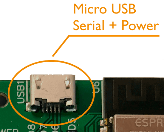
USB
So, to get going with the ESP32 (to upload code) you only need to connect it to your PC using a micro USB cable. This will power the board and provide a data connection to it. SwarmDrive uses a Silicon Labs USB controller chip, you need to have the drivers installed for it. There are many resources available for getting a serial connection to an ESP32 board with the CP210x USB controller.
GPIO
The GPIO connections are available for general use but some of them are located conveniently close to (next to) the motor driver (EN and IN) pins. SwarmDrive comes with jumpers to connect these GPIO’s to the motor driver pins (by default they are installed/connected on delivery). You can also use jumper wires to connect these lines which can be convenient for branching out to an oscilloscope for example.
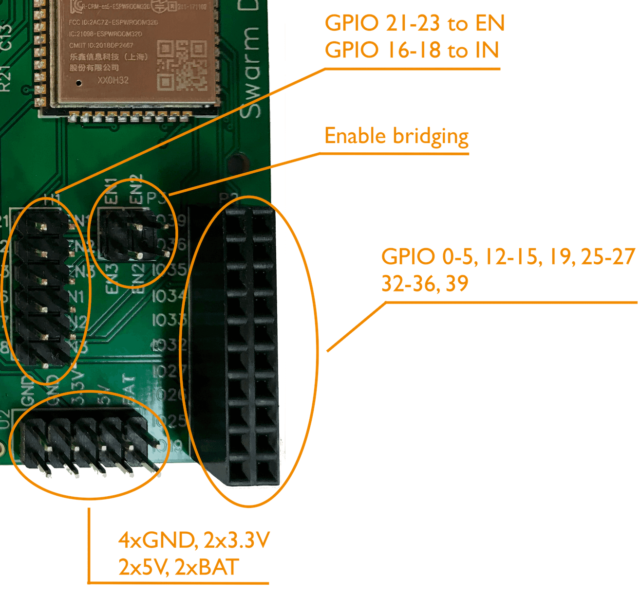
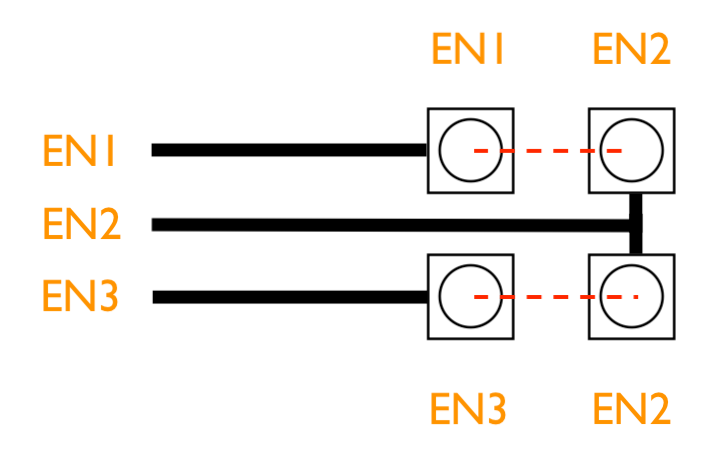
Other pins
Also broken out are 4-GND, 2-3.3V, 2-5V and 2 battery pins. These can be used to power other peripheral components like sensors. The three EN (enable) pins of the L6234 are connected to a bridging connector. This can be used to combine all three EN pins as one pin. If your code will enable all phases together (not separate or by PWM) then you can save two GPIO pins by shorting all three EN pins together as one unit controlled by one GPIO for example.
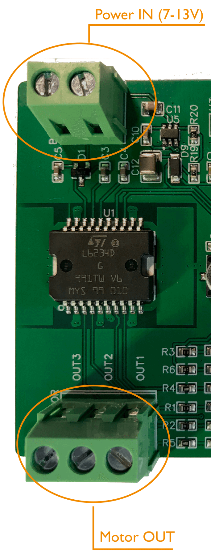
Motor connection
Of course, you will need a BLDC motor of some kind. There are many types of motors, large, small, cheap and expensive. For straightforward experiments you can suffice with a small and cheap gimbal motor (they sell for as low as $10). The three phases are connected to the “motor OUT” connector. The order in which the leads are connected doesn’t matter. You also need to power the motor using the BAT/Power-IN connector. Pay attention to put the leads in with care. The connector needs to grab on to the wires. Sometimes the wire gets under the mechanism and not between the contact plates.
The min/max voltage needed on the BAT/Power-IN connector is rated for 7-13V (also sometimes referred to as 2S-3S when talking LiPo battery lingo). The L6234 motor driver is tolerant to higher voltages but the board is designed in a way where the MCU is on the same power circuit (through a regulator). This means that the maximum Power-IN voltage is just above 13V. To be on the safe side, please do not provide a voltage above 3S (or 13V). If you do not provide power to the BAT/Power-IN connector you can still use the ESP32 MCU by connecting the board using the Micro USB connector. This will power the MCU only and you can upload firmware or monitor the ESP32 output. However it will not power the motor. For that the BAT/Power-IN has to be connected. It is also safe to use both (using USB and BAT/Power-IN at the same time).
As explained above, when you have connected a battery or power supply, the ESP32 is powered by this source too. The buck converter will kick-in and regulate the power to 3.3V to feed the ESP32 if it is not connected to USB anymore. So, for field use you can power the board (with ESP32) and motor together from one power source (battery). To monitor the device (when no longer connected through a serial USB connection) you could use Wi-Fi or Bluetooth. For this to work you will need to setup something like this.
Peripherals
Other peripherals you most likely will need are a potentiometer (value doesn’t matter too much as it will be used purely as a voltage divider) and a rotary encoder. Without these you could start with a very simple open-loop setup but soon you will want to move on to more interesting experimentations.
The potentiometer can be connected to one of the SwarmDrive 3.3V and GND pins with the “wiper” connected to the pin used in your code (the default getting started firmware uses pin 34).
The standard getting started firmware assumes the use of the AMS AS5048B rotary encoder. The firmware code includes a simple but convenient class to read angle values. This encoder can be purchased for around $10-$15 at Digikey or Mouser in a board/adapter formfactor kit with accompanying magnet. The SwarmDrive code uses the “B” type, which is the I2C type. Of course, you can also use other encoders if you write your own interfacing.
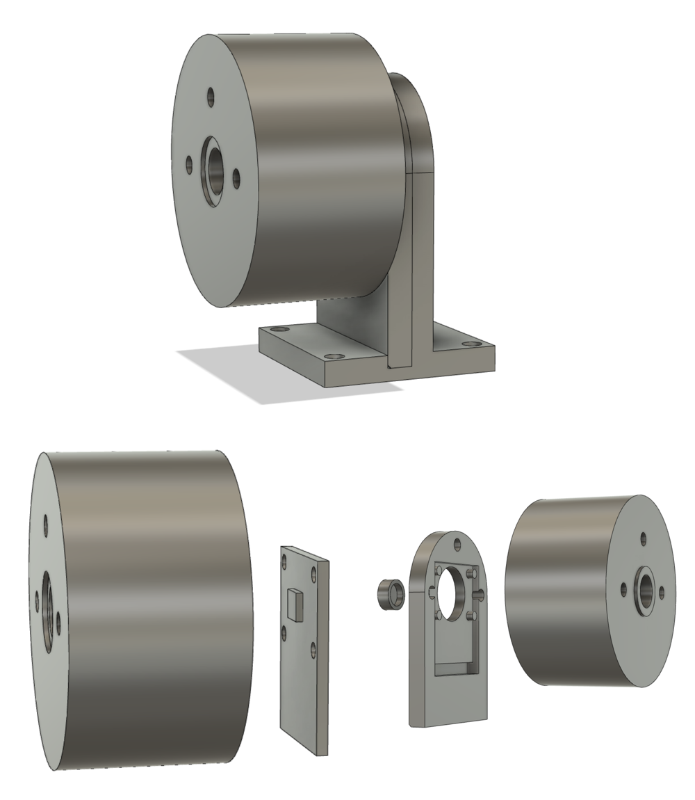
The magnet should be attached to the motor shaft somehow and the AS5048 chip should be mounted close to it. It would be nice to have a 3D printer at hand for this.
Rotary encoder connection
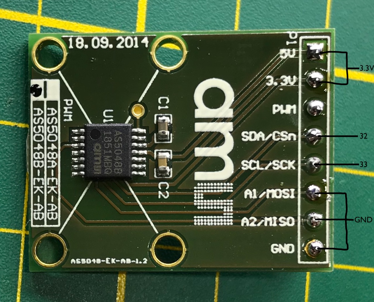
To connect the AS5048B to SwarmDrive you should connect both, the 5V and 3.3V connections to 3.3V on the SwarmDrive board. When using the standard firmware code, SDA and SCL should be connected to GPIO 32 and 33. For the standard I2C address A1 and A2 (together with GND) should be connected to GND on the SwarmDrive board.
Simple Arduino sketch
For the simplest first test, even if you don’t have an environment like PlatformIO running yet, you could just load a simple Arduino sketch. For this you should install the Arduino IDE and install the ESP32 board manager. There are many resources available for guidance.
  const int potPin    = 34;                   // potentiometer pin (connect outer legs to 3.3V and GND)
  const int motorPin1 = 16;                   // motor IN pins
  const int motorPin2 = 17;
  const int motorPin3 = 18;
  const int enable1 = 21;                     // motor EN pins
  const int enable2 = 22;
  const int enable3 = 23;
  const int pwmFreq = 40000;                  // high enough PWM frequency
  int currentStepA = 0;                       // signal array index for coil A
  int currentStepB = 16;                      // signal array index for coil B
  int currentStepC = 32;                      // signal array index for coil C

  // signal array
  int pwmSin[] = {127,110,94,78,64,50,37,26,17,10,4,1,0,1,4,10,17,26,37,50,64,78,94,110,127,144,160,176,191,204,217,228,237,244,250,253,255,253,250,244,237,228,217,204,191,176,160,144,127}; // array of PWM duty values (sine)

  void setup() {
    ledcSetup(0, pwmFreq, 8);                 // channel (0,1 and 2) setup for PWM with PWM frequency and resolution (8 bits)
    ledcSetup(1, pwmFreq, 8);
    ledcSetup(2, pwmFreq, 8);
    ledcAttachPin(motorPin1, 0);              // attach pins to channel
    ledcAttachPin(motorPin2, 1);
    ledcAttachPin(motorPin3, 2);

    pinMode(potPin, INPUT);                   // pinmode pot and enable pins
    pinMode(enable1, OUTPUT);
    pinMode(enable2, OUTPUT);
    pinMode(enable3, OUTPUT);
    digitalWrite(enable1, HIGH);              // enable coils
    digitalWrite(enable2, HIGH);
    digitalWrite(enable3, HIGH);
  }

  void loop() {
    currentStepA = currentStepA + 1;          // increment coilA signal step index
    currentStepB = currentStepA + 16;         // set coilB 120 degrees further (1/3 of full cycle)
    currentStepC = currentStepA + 32;         // set coilC 240 degrees further (2/3 of full cycle)

    currentStepA = currentStepA%48;           // adjust overflow of array index
    currentStepB = currentStepB%48;
    currentStepC = currentStepC%48;

    ledcWrite(0, pwmSin[currentStepA]*0.5);   // write PWM duty cycle values (0.5 = half power to avoid overheating)
    ledcWrite(1, pwmSin[currentStepC]*0.5);
    ledcWrite(2, pwmSin[currentStepB]*0.5);

    int sensorValue = analogRead(potPin);

  //  Choose mode by uncommenting/commenting one of three below:
  //  delay(sensorValue/100);                   // speed controlled by pot
  //  currentStepA = sensorValue/5;             // position controlled by poy
    delay(1);                                 // constant speed
  }