SwarmDrive
The SwarmDrive board originated from a research project consisting of hardware and software to drive electric motors, more specific BLDC motors, using an ESP32.
Introduction
In a quest for knowledge surrounding technology related to movement control, most come across the realm of electric motors. Many times these seemingly primitive devices that force a shaft to spin using magnetic fields are ignored to explore further. Most engineers know its principle working and think it to be fairly simple. But when needed to know more about the detailed working of a BLDC (Brushless DC) motor, a whole new world revealed itself. Of course, the basic principle doesn’t change, but how to use this rather primitive way of spinning a shaft (or rotor, which also can be the outer shell of a motor) using a micro controller can open up a whole new category of interesting theoretical paths to explore.
When starting to do more research it quickly becomes clear that there is a lot of information available, but it will be a challenging to combine the pieces for a specific goal to drive a motor using a micro controller and building the firmware for such. What we have in mind, most times, are things like a gimbal or a robotics device of some sort. There are enough reasons to master this “old” tool for new things.
Why an ESP32?
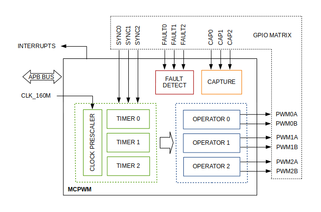
Simpel. Many technology enthusiasts love this amazing powerful and versatile MCU, from which most still only even scratched the surface of what its possibilities are. Among these capabilities there is the MCPWM unit, intended for controlling a motor.
Now, there are more powerful or less powerful MCU’s like Atmel, STM, PIC, etc. Many to choose from nowadays. But the ESP32 is fairly mainstream nowadays and should be capable enough for the basic things most want to accomplish.
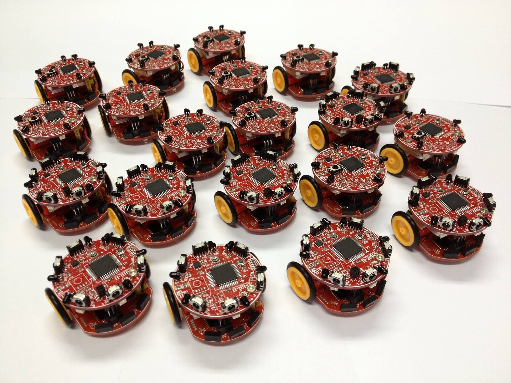
One other feature of the ESP32 of course is its communication capability (Bluetooth and Wi-Fi). That’s how the name “SwarmDrive” arose. The idea of having multiple motor/driver combinations in projects without hard wired connections. Be able to remotely control motor combinations or let devices communicate among each other like a swarm. Perhaps “ESP-Now” can play a role in such a setup, at least something to explore.
Motor Driver
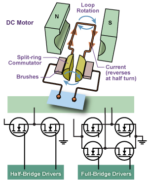
To send the high current through the motor coils to let the magnetism unleash its power it is needed to have some sort of switching device for switching (commutate) between the coils and/or to rapidly switch current on and off to have a mechanism to vary the power a coil is getting to work with. For a “normal” DC motor this is done mechanically by using a brush dragging over the contacts attached to the shaft. For a brushless motor FETs can be used, configured in a half bridge configuration. That’s only the core element, the fundamental basics.
These switches (FETs) or complete half bridges can, to a certain limit, be integrated into a chip called a motor driver. Of course, if the currents are too high, the FETs will need to be discrete components as they need to dissipate the heat that will be formed due to switching losses. In this case a gate driver is used (integrated FETs driving discrete FETs).
Around the core switching setup there can be lots of circuitry for other tasks. Most important the task of switching at the right time. The timing for a brushed motor is done mechanically by the brushes. For a brushless motor there needs to be some electronic alternative. This and other parts of a motor system can also be integrated (partly) in a motor driver chip. This can even go as far as integrating a complete MCU plus firmware.
Besides the functional intentions for SwarmDrive to use it for motion functions, it would also be fun to learn the inner workings of such systems. For that reason, it was chosen not to use an all in one black box motor driver chip solution but instead use a basic half bridge chip that can power a motor up to a usable level. Not intended for power applications like a bike or scooter but for experimenting with motion on the scale of a gimbal or small robot device. After learning about the ins and outs on a smaller scale this can be used to crank it up to a bigger scale. The algorithms and principles stay the same.
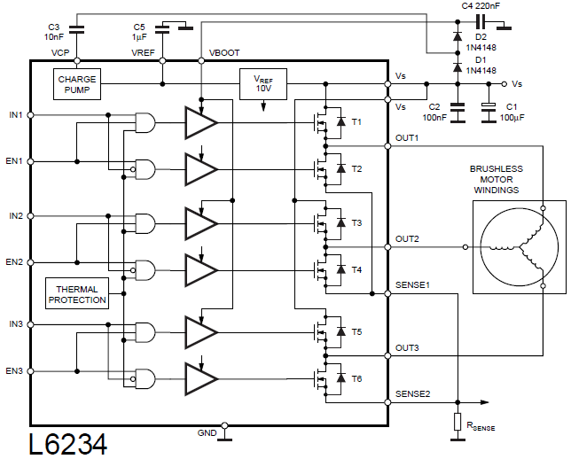
The L6234 from STMicroelectronics, a well known basic three-phase motor driver, was chosen for these reasons.
Where to start
When getting ready to do some first experiments to fathom the exact working of a so-called ESC (Electronic Speed Controller) one can look at several existing (open source) projects like the VESC project (vesc-project.com). But most of these are in an advanced stage and will not suit a very basic discovery mode when wanting to start from ground zero. Having a basic development board with the two main components (MCU and driver) integrated together with power and connectivity would make life a lot easier. The first goal should be just to get a motor spinning using basic code, no libraries, to translate the seemingly simple theory to a practical working example. One extra component of course is needed, a motor. For a simple experimental setup this can be a very cheap (tiny and just a few dollar) one, such as a 2206-140Kv Brushless Gimbal Motor (although just one step bigger would run more smoothly).
Choosing a motor can be a challenge by itself already. Especially if not knowing anything about Kv, what coil resistance to use and many other ins and outs about BLDC motors. Proof once again that the assumption of electric motors being simple primitive devices is not entirely accurate. After doing some research it can be concluded that for basic testing purposes a small gimbal motor with relative high coil resistance would be a good choice.
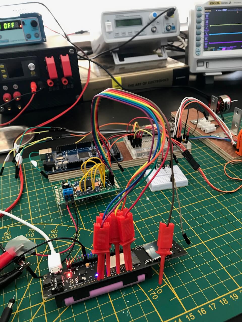
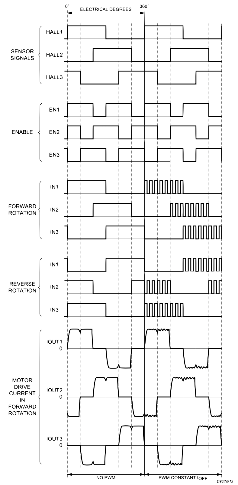
It wouldn’t hurt to study the L6234 application note document (AN1088) to try to get the wave forms as depicted in fig. 17 of that same document on a scope screen. This will help to get the motor spinning in a crude way, it will make you do some thinking, sketching (truth tables and such) and reading to get everything between the ears. That is, the exact details on how to look at this (the enable sequence and the IN sequence). If you look at fig. 17 closely you see that the motor current (bottom) and EN sequence for the three coils is 120 degrees shifted which is what you want (360 / 3 coils). Questions arise like what the differences are between a theoretical 3-coil motor and a real multi coil pairs motor. How does this affect things? Now, this leads to the following;
Being able to measure things with a scope, how to measure the coil currents? This can be challenging. A virtual ground is needed to measure voltages across a three-phase configuration. This can be done using a star shape resistor network but still there will be a lot of fine-tuning left to do on the scope settings. At the end you will manage to get a feel for it and manage to get a somewhat similar graph on the scope (with some filtering needed).
Further understanding will evolve in the meantime. For example you will find out early that this crude (open loop) mimicking of the brushed commutation is a bit too crude. Nothing more than the brute pulling/pushing of the rotor at the pace of the loop that is sending voltage to the coils. Using and varying PWM signals will have no effect on the speed (the commutation loop will still drive the speed of switching from one coil to another).
More reading and research will reveal more sophisticated ways of doing things like FOC and SVPWM (using Space Vector PWM). But this can open up a whole world yet again!
Doing tedious experiments of changing code, recompile, re-flash, code iterations, you soon find out that you need some sort of real time mechanism to fiddle with parameters and see wat the effects are. It would be nice to have some sort of crude UI or a console to operate the code experiments before moving on. That’s how the console library came about. For the real time aspect of having accurate timing for the motor commutation and the concurrent aspect of a console running side by side it’s almost unavoidable to use the ESP-IDF FreeRTOS based framework to build it. RTOS was made for this. Read more about it in the firmware section.
Moving on to SVM and FOC
Now, this Space Vector steering of the magnetic flux field is a whole new approach to commutation. You soon develop a feeling of feeding current proportional to the coils to put the rotor in a certain position or to use a sine wave to do this continues. But what are the fine details? When you try to lookup information about this, you either end up on over simplified web articles or over complicated mathematical papers from the scientific community. The “hobby” engineer approach can be hard to find.
One masterpiece of course in this category is the “teaching old motors new tricks” series by Dave Wilson from TI. This is a must for everyone starting out in this field. But still it will even generate more questions. Questions that only can be answered by experiments.
More theory
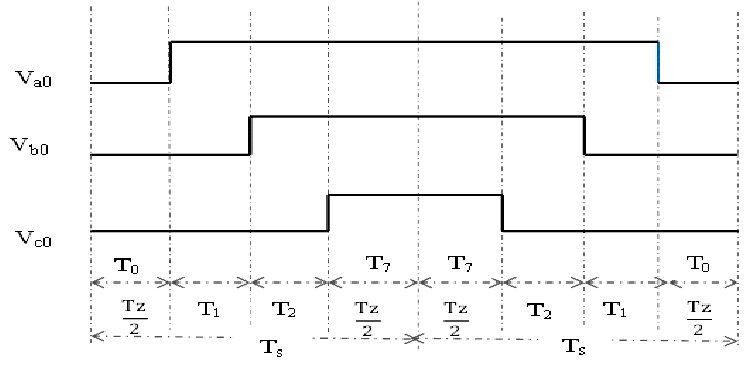
In a nutshell you first have to understand that you can bring or set the rotor in a particular position by sending the right amount of current through two coils. It’s like attaching two ropes to the rotor and pulling from two sides. Pulling a bit more (longer) on one side pulls the rotor towards this side. But keep pulling the other side (in bursts) to keep a balance. The way this can be done is with a symmetrical PWM pattern. The above mentioned video series of Dave Wilson has a nice simulation (about half an hour into part three). You have to understand that a symetrical PWM "pulls" with two coils with varying duration in an alternating way with a short pause (when all three coils are activated). The sequence (or timing) of this symmetrical PWM is in such a pattern that the pulling bursts are just right for a certain position (vector). Dave Wilson does a great job of explaining this pattern and it would be of no use to try to repeat his talk here. Part 3 of his series explains it very well.
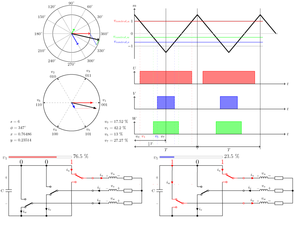
You finally will start to understand these strange SVM wave forms and in particular this mysterious 15% extra power or voltage that can be utilized by this approach. It can take a while to understand where this strange triangular wave form comes from when looking at diagrams. A lecture of Prof. L. Umanand of the Indian Institute of Science (“lecture”) could help with this.
Also, one small but important detail is the notion of maximum torque that can be accomplished by applying an angle of 90 degrees. You realize that in open loop experiments the rotor is held back due to the synchronized relation between the magnetic flux and the rotor angle. This 90-degree concept is similar to the stick and carrot approach.
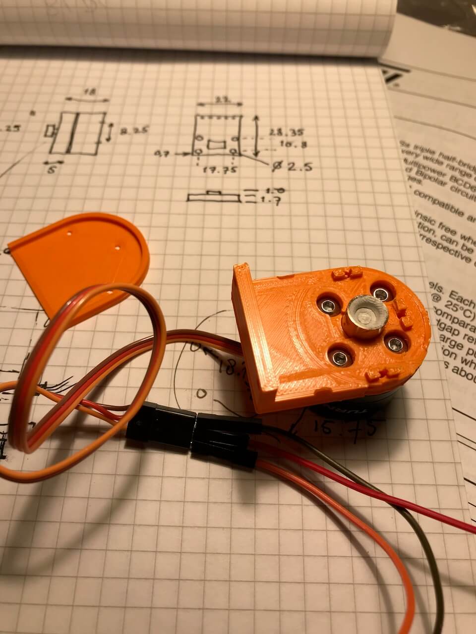
In short, a closed loop is needed where SVM (symmetrical PWM) is used to steer the rotor to a position 90 degrees further from its last known position. And repeat this as fast as possible (if speed was the target). To read the current rotor position a AS5048 rotary position sensor can be used. This cheap device can be attached to the motor easily by using some sort of 3D printed holder for it. The “B” variant uses I2C which is fast enough for experimenting and easy to interface with. A simple library for this is included in the code in the SwarmDrive repository on GitHub.
Using the example SwarmDrive code, the difference can be spectacular already. The little motor will spin like crazy and much smoother. However, this code is by no means perfect, it is merely intended as a starting point to get up and running quickly. Many questions to answer still and lots of goals to achieve.
Find out what parameters like angle, PWM duty cycle, PWM frequency, step frequency, etc. are doing. How, how often and how accurate to measure the actual angle of the rotor. How to accurately set a desired position in steps or turns plus angle like a stepper motor. How to maximize torque in doing so without over shooting the target position i.e. how to get to a target position as fast as possible without over shoot. What is needed to apply PID-like code to do so, and many more questions to answer and goals to set.